BFS17P
NPN Silicon RF Transistor
Features
•
•
•
•
•
•
•
•
•
Maximum collector-emitter voltage VCE0 = 15 V
Maximum collector current IC = 25 mA
Noise figure NF = 3.5 dB
3rd order output intercept point OIP3 = 21.5 dBm
1 dB output compression point P-1dB = 10 dBm
Transition frequency fT = 1.4 GHz
Maximum total power dissipation Ptot = 280 mW
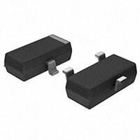
Package: SOT23
Pb-free (RoHS compliant) package
Potential Applications
•
•
For broadband amplifiers up to 1 GHz at collector currents from 1 mA to 20 mA
For mixers and oscillators in sub-GHz applications
Device Information
ESD (Electrostatic discharge) sensitive device, observe handling precaution!
Type / Ordering code
Marking
BFS17P / BFS17PE6327HTSA1
MCs
Datasheet
www.infineon.com
Pin Configuration
1=B
2=E
3=C
Please read the Important Notice and Warnings at the end of this document
Package
SOT23
Revision 1.1
2017-06-01
�BFS17P
NPN Silicon RF Transistor
Table of contents
Table of contents
Features . . . . . . . . . . . . . . . . . . . . . . . . . . . . . . . . . . . . . . . . . . . . . . . . . . . . . . . . . . . . . . . . . . . . . . . . . . . . . . . 1
Potential Applications . . . . . . . . . . . . . . . . . . . . . . . . . . . . . . . . . . . . . . . . . . . . . . . . . . . . . . . . . . . . . . . . . . 1
Device Information . . . . . . . . . . . . . . . . . . . . . . . . . . . . . . . . . . . . . . . . . . . . . . . . . . . . . . . . . . . . . . . . . . . . . 1
Table of contents . . . . . . . . . . . . . . . . . . . . . . . . . . . . . . . . . . . . . . . . . . . . . . . . . . . . . . . . . . . . . . . . . . . . . . . 2
1
Maximum Ratings . . . . . . . . . . . . . . . . . . . . . . . . . . . . . . . . . . . . . . . . . . . . . . . . . . . . . . . . . . . . . . . . . . . . . . 3
2
Thermal Resistance . . . . . . . . . . . . . . . . . . . . . . . . . . . . . . . . . . . . . . . . . . . . . . . . . . . . . . . . . . . . . . . . . . . . . 3
3
Electrical Characteristics . . . . . . . . . . . . . . . . . . . . . . . . . . . . . . . . . . . . . . . . . . . . . . . . . . . . . . . . . . . . . . . .4
4
Typical characteristics diagrams . . . . . . . . . . . . . . . . . . . . . . . . . . . . . . . . . . . . . . . . . . . . . . . . . . . . . . . . 5
5
5.1
Package information . . . . . . . . . . . . . . . . . . . . . . . . . . . . . . . . . . . . . . . . . . . . . . . . . . . . . . . . . . . . . . . . . . . .9
SOT23 package . . . . . . . . . . . . . . . . . . . . . . . . . . . . . . . . . . . . . . . . . . . . . . . . . . . . . . . . . . . . . . . . . . . . . . . . . .9
Revision History . . . . . . . . . . . . . . . . . . . . . . . . . . . . . . . . . . . . . . . . . . . . . . . . . . . . . . . . . . . . . . . . . . . . . . . 10
Trademarks . . . . . . . . . . . . . . . . . . . . . . . . . . . . . . . . . . . . . . . . . . . . . . . . . . . . . . . . . . . . . . . . . . . . . . . . . . . 11
Datasheet
2
Revision 1.1
2017-06-01
�BFS17P
NPN Silicon RF Transistor
Maximum Ratings
1
Maximum Ratings
Table 1
Maximum Rating at TA = 25 °C, unless otherwise specified
Parameter
Symbol
Values
Unit
Note or Test Condition
Collector-emitter voltage
VCEO
15
V
–
Collector-base voltage
VCBO
25
–
Emitter-base voltage
VEBO
2.5
–
Collector current
IC
25
Peak collector current
ICM
50
Total power dissipation 1)
Ptot
Junction temperature
mA
–
280
mW
TS ≤ 95 °C
Tj
150
°C
–
Ambient temperature
TA
-65 ... 150
Storage temperature
TStg
-65 ... 150
2
–
Thermal Resistance
Table 2
Thermal resistance
Parameter
Symbol
Values
Unit
Note or Test Condition
Junction - soldering point
RthJS
≤ 195
K/W
–
Note:
1
For calculation of RthJA please refer to Application Note AN077 (Thermal Resistance Calculation)
TS is measured on the collector lead at the soldering point to the pcb
Datasheet
3
Revision 1.1
2017-06-01
�BFS17P
NPN Silicon RF Transistor
Electrical Characteristics
3
Table 3
Electrical Characteristics
DC Characteristics at TA = 25°C, unless otherwise specified
Parameter
Symbol
Values
Min.
Typ.
Max.
Unit
Note or Test Condition
Collector-emitter breakdown
voltage
V(BR)CEO
15
–
–
V
IC = 1 mA, IB = 0
Collector-base cutoff current
ICBO
–
–
0.05
µA
VCB = 10 V, IE = 0
–
–
10
VCB = 25 V, IE = 0
Emitter-base cutoff current
IEBO
–
–
100
µA
VEB = 2.5 V, IC = 0
DC current gain
hFE
40
–
150
–
IC = 2 mA, VCE = 1 V
pulse measured
20
70
–
–
0.1
0.4
Collector-emitter saturation
voltage
Table 4
VCEsat
V
IC = 10 mA, IB = 1 mA
Unit
Note or Test Condition
GHz
IC = 2 mA, VCE = 5 V,
f = 200 MHz
AC Characteristics at TA = 25°C, unless otherwise specified
Parameter
Transition frequency
Symbol
fT
Values
Min.
Typ.
Max.
1
1.4
–
1.3
2.5
–
0.8
Collector-base capacitance
Ccb
–
0.55
Collector emitter capacitance
Cce
–
0.27
Emitter-base capacitance
Ceb
–
0.9
Minimum noise figure
NFmin
–
Transducer gain
|S21e|2
Third order intercept point at
output
1dB compression point
Datasheet
IC = 25 mA, VCE = 1 V
pulse measured
IC = 25 mA, VCE = 5 V,
f = 200 MHz
pF
VCB = 5 V, f = 1 MHz,
VBE = 0 , emitter grounded
pF
VCE = 5 V, f = 1 MHz,
VBE = 0 , base grounded
1.45
pF
VEB = 0.5 V, f = 1 MHz,
VCB = 0 , collector grounded
3.5
5
dB
IC = 2 mA, VCE = 5 V,
ZS = 50Ω, f = 800 MHz
–
13
–
dB
IC = 20 mA, VCE = 5 V,
ZS = ZL = 50Ω, f = 500 MHz
OIP3
–
21.5
–
dBm
VCE = 5 V, IC = 20 mA,
f = 800 MHz, ZS = ZSopt,
ZL = ZLopt
P-1dB
–
10
–
dBm
IC = 20 mA, VCE = 5 V,
ZS = ZL = 50Ω, f = 800 MHz
4
Revision 1.1
2017-06-01
�BFS17P
NPN Silicon RF Transistor
Typical characteristics diagrams
4
Figure 1
Typical characteristics diagrams
Total Power Dissipation
R thJS [K/W]
10 3
10 2
D=0
D = .005
D = .01
D = .02
D = .05
D = .1
D = .2
D = .5
10 1
10 0
10 -6
10 -5
10 -4
10 -3
10 -2
10 -1
10 0
t p[sec]
Figure 2
Datasheet
Permissible Pulse Load RthJS = f (tp)
5
Revision 1.1
2017-06-01
�BFS17P
NPN Silicon RF Transistor
Typical characteristics diagrams
P tot max / P tot DC [W]
100
D=0
D = .005
D = .01
D = .02
D = .05
D = .1
D = .2
D = .5
10
1
10 -6
10 -5
10 -4
10 -3
10 -2
10 -1
10 0
t p [sec]
Figure 3
Permissible Pulse Load Ptotmax / PtotDC = f (tp)
50
I B =429µA
45
P tot = 280mW
I B =382µA
40
I B =336µA
I C [mA]
35
I B =289µA
30
I B =243µA
25
I B =196µA
20
I B =150µA
15
I B =103µA
10
I B =57µA
5
0
I B =10µA
0
2
4
6
8
10
12
V CE [V]
Figure 4
Datasheet
Collector current IC = f(VCE), IB = parameter
6
Revision 1.1
2017-06-01
�BFS17P
NPN Silicon RF Transistor
Typical characteristics diagrams
160
140
120
hfe
100
80
60
40
20
0
5
10
15
20
25
30
I C [mA]
Figure 5
Current gain hFE= f(IC), VCE = 8 V
1
C
0.9
CB
C
EB
0.8
0.7
C [pF]
0.6
0.5
0.4
0.3
0.2
0.1
0
0
5
10
15
20
V CB ; VEB [V]
Figure 6
Datasheet
Collector-Base CCB=f(VCB); Emitter-Base Capacitance CEB=f(VEB)
7
Revision 1.1
2017-06-01
�BFS17P
NPN Silicon RF Transistor
Typical characteristics diagrams
3.5
3
10V
5V
fT [GHz]
2.5
3V
2
2V
1.5
1
1V
0.5
0
0
5
10
15
20
25
30
IC [mA]
Figure 7
Datasheet
Transition frequency fT = f(IC), VCE = parameter
8
Revision 1.1
2017-06-01
�BFS17P
NPN Silicon RF Transistor
Package information
5.1
SOT23 package
2.9 ±0.1
B
1
1)
0.25 M B C
0.4 +0.1
-0.05
0.1 MAX.
2.4 ±0.15
3
1 ±0.1
2
0.2
C
0.95
M
1.3 ±0.1
5
0.15 MIN.
Package information
0.08...0.1
A
1) Lead width can be 0.6 max. in dambar area
SOT23-PO V08
SOT23 package outline
Soldering Type: Wave Soldering
0.8
0.9
0.8
1.2
0.8
SOT23-FPR V08
1.6
1.2
SOT23-FPW V08
1.4 MIN.
0.8
0.9
1.3
Transport
direction
1.4 MIN.
Soldering Type: Reflow Soldering
Figure 9
A
0...8˚
1.9
Figure 8
5
SOT23 foot frint
Manufacturer
EH s
2005, June
Date code (YM)
BCW66
Type code
Pin 1
Figure 10
SOT23 marking layout (example)
4
0.2
2.65
8
2.13
0.9
Pin 1
3.15
1.15
SOT23-TP V02
Figure 11
Datasheet
SOT23 tape and reel
9
Revision 1.1
2017-06-01
�BFS17P
NPN Silicon RF Transistor
Revision History
Revision History
Major changes since previous revision
Revision History
Reference
Description
All pages
2017-06-01: Conversion to new document template
RthJS
2017-06-01: Update of value
Datasheet
10
Revision 1.1
2017-06-01
�Trademarks
All referenced product or service names and trademarks are the property of their respective owners.
Edition 2017-06-01
Published by
Infineon Technologies AG
81726 Munich, Germany
© 2017 Infineon Technologies AG
All Rights Reserved.
Do you have a question about any
aspect of this document?
Email: erratum@infineon.com
Document reference
IFX-kwg1493983596879
IMPORTANT NOTICE
The information given in this document shall in no
event be regarded as a guarantee of conditions or
characteristics (“Beschaffenheitsgarantie”) .
With respect to any examples, hints or any typical values
stated herein and/or any information regarding the
application of the product, Infineon Technologies
hereby disclaims any and all warranties and liabilities of
any kind, including without limitation warranties of
non-infringement of intellectual property rights of any
third party.
In addition, any information given in this document is
subject to customer’s compliance with its obligations
stated in this document and any applicable legal
requirements, norms and standards concerning
customer’s products and any use of the product of
Infineon Technologies in customer’s applications.
The data contained in this document is exclusively
intended for technically trained staff. It is the
responsibility of customer’s technical departments to
evaluate the suitability of the product for the intended
application and the completeness of the product
information given in this document with respect to such
application.
WARNINGS
Due to technical requirements products may contain
dangerous substances. For information on the types
in question please contact your nearest Infineon
Technologies office.
Except as otherwise explicitly approved by Infineon
Technologies in a written document signed by
authorized representatives of Infineon Technologies,
Infineon Technologies’ products may not be used in
any applications where a failure of the product or
any consequences of the use thereof can reasonably
be expected to result in personal injury
�